|
|
|||||||||
|
|
|
|
|
|
|
|
|
|
|
This appendix contains the following information.
This appendix provides guidelines for defining the optimized technology section in the LEF file to get the best performance using Cadence® place-and-route tools.
For the following guidelines, the preferred routing direction for metal1 and all other odd metal layers is horizontal. The preferred routing direction for metal2 and all other even metal layers is vertical. Standard cells are arranged in horizontal rows.
This appendix discusses the following LEF statements.
The following is a summary for choosing the right pitch for an existing design library. For detailed information on determining routing pitch, refer to the Cadence Abstract Generator User Guide.
|
Minimum width of metal1 = 0.23 μm |
|
|
Minimum space between two metal1 regions = 0.23 μm |
|
|
Minimum and maximum width of cut1 = 0.26 μm |
|
|
Minimum extension of metal1 beyond cut1 = 0.01 μm |
|
|
Minimum width of metal3 = 0.28 μm |
|
|
Minimum space between two metal3 regions = 0.28 μm |
|
|
Minimum and maximum width of cut2 = 0.26 μm |
|
|
Minimum extension of metal1 beyond cut2 = 0.01 μm |
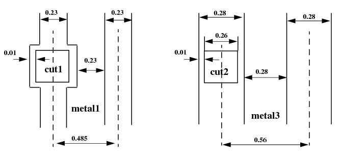
Although the minimum metal1 routing pitch is 0.485um from the design rule, you should use 0.56um instead, to match the metal3 routing pitch in the same preferred direction.

|
Align the routing pitch for metal1 and metal2, with the pins inside the standard cells. |
|
|
Have uniform routing pitch in the same preferred direction. The pitch ratio should be 2 - 3 or 1 - 2. It is better to define the metal1 pitch larger than necessary in order to achieve a 1 - 1 ratio because the metal1 width is usually smaller the metal2 and metal3 widths. |
|
|
The height of the cell should be the even multiple of the metal1 pitch, and the width of the cell should be the even multiple of the metal2 pitch. |
|
|
The blockage modeling, especially for metal1, should be simplified as much as possible. For example, it is very common for the entire area within the cell boundary to be obstructed in metal1, so use a single rectangular blockage instead of many small blockages. |
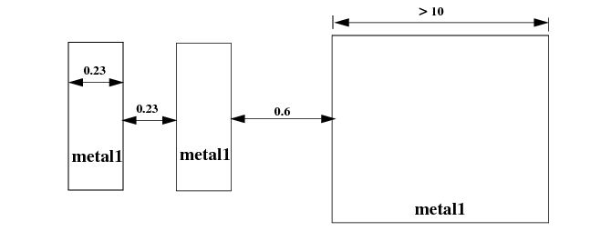
The SPACING statement in the LEF LAYER section is applied to both regular and special wires. You can use the Cadence® ultra router option frouteUseRangeRule to determine which objects to check against the SPACING RANGE statement. The default checks both pin and obstruction.
|
Minimum space between two metal1 regions = 0.23 μm |
|
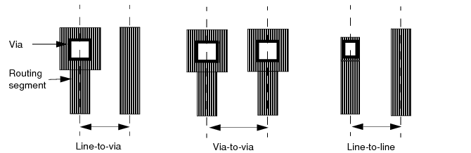
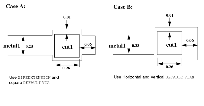
The following guidelines are for wire extension at vias.
|
Minimum and maximum width of cut1 = 0.26 μm |
|
|
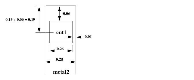
Minimum width of metal2 = 0.28 μm |
|
|
Minimum extension of metal2 beyond cut1 = 0.01 μm |
|
|
Minimum extension of metal2 end-of-line region beyond cut1 = 0.06 μm |
|
|
Use the WIREEXTENSION statement instead of defining multiple vias because the width of the metal2 in cut1 is the same as the default routing width of the metal2 layer. |
|
|
The WIREEXTENSION statement only extends wires and not vias. For 65nm and below, WIREEXTENSION is no longer recommended because it may generate some advance rule violations if wires and vias have different widths. |
|
|
Define the DEFAULT VIA as a square via. |
The following guidelines are for default vias.
|
Minimum width of metal1 = 0.23 μm |
|
|
Minimum and maximum width of cut1 = 0.26 μm |
|
|
Minimum extension of metal1 beyond cut1 = 0.01 μm |
|
|
Minimum extension of metal1 end-of-line region beyond cut1 = 0.06 μm |
|
|
If the width of the end-of-line metal extension is the same as the default metal routing width, as in Case A, use the WIREEXTENSION statement in the LEF LAYER section, and define a square via in the DEFAULT VIA section. |
|
|
If the width of the end-of-line metal extension is the same as the width of the via metal, as in Case B, define one horizontal DEFAULT VIA and one vertical DEFAULT VIA to cover the required metal extension area in both pregerred and non-preferred routing directions. Do not use the WIREEXTENSION statement in the LEF LAYER section. |
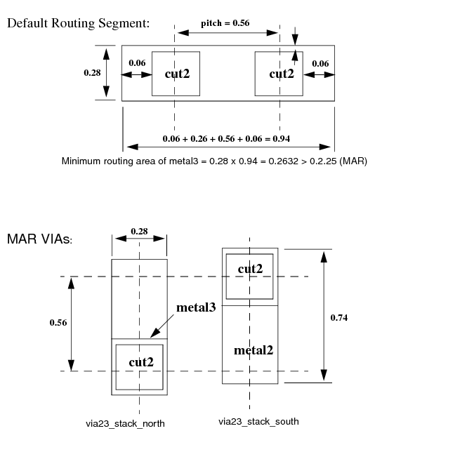
The following guidelines are for stack vias (minimum area rule) and SAMENET SPACING.
|
Minimum width of metal2 = 0.28 μm |
|
|
Minimum and maximum width of cut2 = 0.26 μm |
|
|
Minimum extension of metal2 beyond cut2 = 0.01 μm |
|
|
Minimum area of metal2 = 0.2025 μm |
|
|
Cut2 can be fully or partially stacked on cut1, contact or any combination |
|
|
Minimum width of metal3 = 0.28 μm |
|
|
Minimum and maximum width of cut3 = 0.26 μm |
|
|
Minimum extension of metal2 beyond cut3 = 0.01 μm |
|
|
Minimum area of metal3 = 0.2025 μm |
|
|
Cut3 can be fully or partially stacked on cut2, cut1, contact or any combination |
|
|
If vias are stackable, create the TOPSTACKONLY vias with a rectangular shape blocking only one neighboring grid for both sides of the preferred routing direction. In other words, one north oriented and one south oriented for vertical-preferred routing layers, and one east oriented and one west oriented for horizontal-preferred routing layers. |
|
|
The STACK keyword in the SAMENETSPACING statements only allows vias to be fully overlapped (stacked) by SROUTE commands. To allow vias to be partially overlapped, set the environment variable SROUTE.ALLOWOVERLAPINSTACKVIA to TRUE. |
|
|
The metal1 layer does not require a MAR via because all metal1 pins should satisfy the minimum area rules. |