
This section is a short introduction to the terminology of asic making.
The end product of a vlsi design flow is basically a drawing. This drawing is what you send to the foundry in order to fabricate it. Usually, this is a file in gds format, which contains a lot of geometric shapes expressed in microns or nanometers.
This drawing is called a layout.
In the layout, each geometrical shape is associated with a layer. For example, there are layers for each metal level like metal1 or metal2.
Layers tells in what material you want the geometrical shape to be build. (this is an oversimplification)
All shapes in a given layer constitute a mask, analogous to an overlay in classical drawing programs.
The foundry will not accept any layout. In order to be successfully fabricated, all the shapes of a layout must respect a set of rules. For example, to ensure that after fabrication, two separated shapes of metal1 are indeed separated, they must respect a minimal distance, for example 0.5µ. This special set of rules is called the Design rules.
Design Rules gives many insigth about a process and is subjected to nda. For the same reason your whole layout covered by it, meaning that you cannot publish it in any way.
Symbolic Layout is a way of making the layout of a chip independant of a given technological node. This technique is based on the observation that, between two processes in the same technological node (say, for example, 350nm of ams and 350nm of tsmc), there are only minors rules variations. Moreover, even between different nodes (350nm ams and 180nm ams), the shrink rate of the various layers of the process are the same.
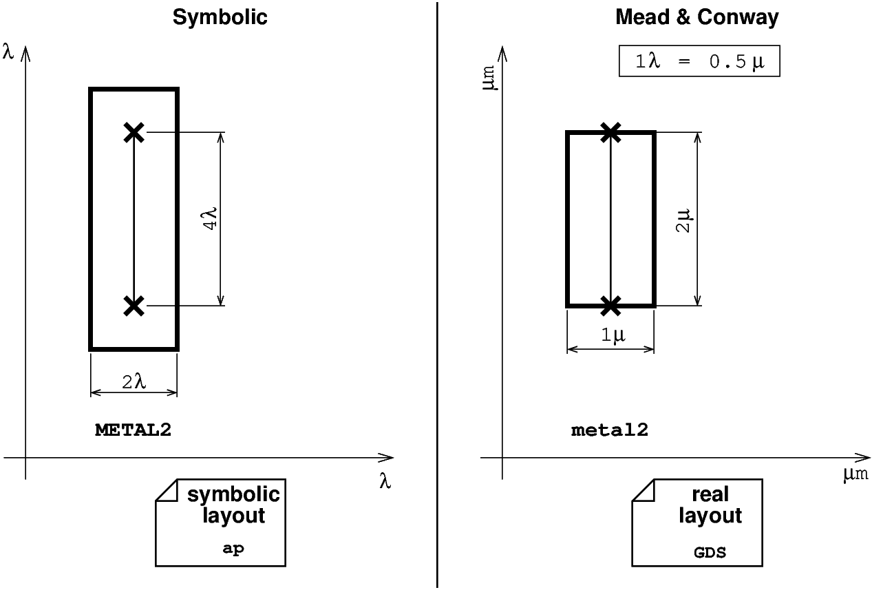
Symbolic layout consist of drawing in a blank unit called the λ (lambda). Then, the value of the λ is calculated for the target technology so that the layout fit it's particular design rules. This approach was first introduced by Mead & Conway [VLSISYS].
As Coriolis can manage both symbolic and real layers in the same design, it uses the following convention for layer naming:
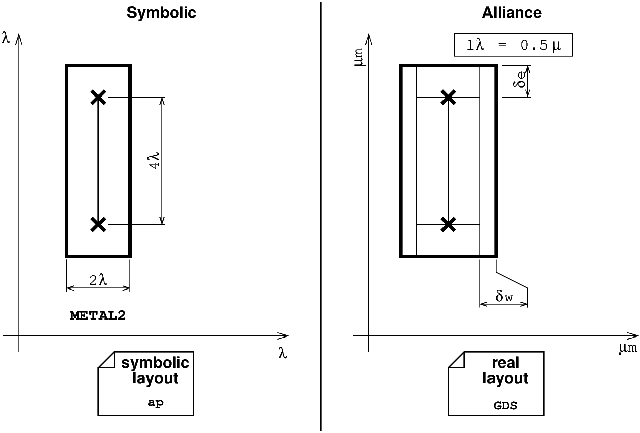
The symbolic layout of Alliance, refine this approach, by adding width and cap extentions factors to allow a closer fitting of the technology.
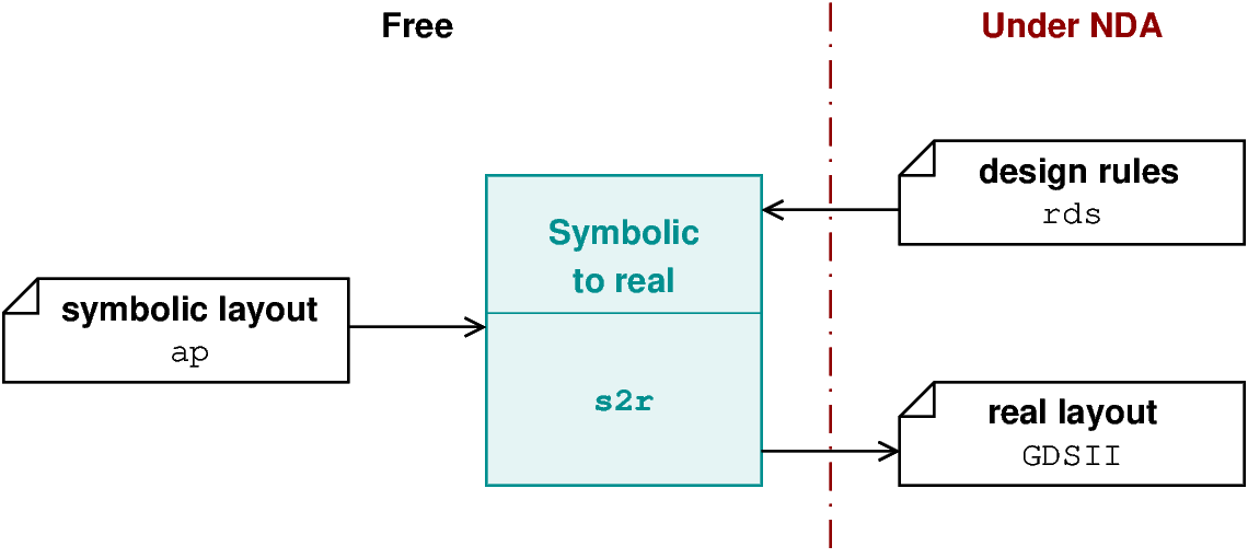
Contrary to commercial design flows wich directly creates a layout for a target node, our flow create a symbolic layout which you have to translate into one on the target process. This is done with the s2r tool which stands for "Symbolic To Real". And this tool must have a configuration file for the intended technology (this is the .rds file). As the .rds file is written using the Design Rules so is under nda. Writting the .rds to get the best fit for target process is still largely a craft.
Cons:
Pros:
The symbolic layout approach is not suited for analog designs. Analog designs are closely related to the target process. So we developped a different methodology to ensure portability.
| [VLSISYS] | Mead, Carver; Conway, Lynn (1980). Introduction to VLSI systems. Reading, Mass.: Addison-Wesley. ISBN 0201043580. OCLC 4641561 |